This system marks the transition from single station pin clocks (see I.D. 50) 
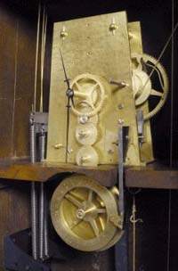
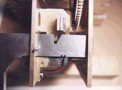
to central station systems that use electric circuits as the connection from several remote stations to a central recorder. In this early device, rather than electric wires to connect the remote stations to the central recorder, iron wires are used to transmit mechanical motion when the watchman "pulls" each remote station. 

Edward Howard, who subsequently developed a more practical version of the present unit (see I.D. 494) as well as the first widely accepted electric system (see I.D. 496), had made mechanical units like that pictured here when in partnership with David Davis in the 1850s.  Before that they both had 
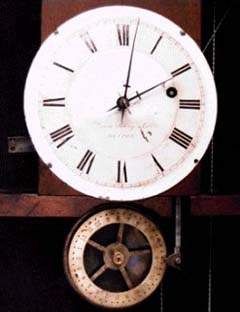
been exposed to similar devices while apprenticed to the younger Aaron Willard. A unit at the Peabody & Essex Museum, Salem MA., marked "Aaron Willard," operates on the same system of levers that is used in this Davis & Polsey clock. The Peabody & Essex clock is likely to have been made in England by one of the regular suppliers to Willard, particularly Robert Roskell.  Another unit, at the Willard House and Clock Museum, Grafton, MA., is marked "A. Willard, Jr."  It seems to be an unfinished inventor's model that was an attempt to work out the mechanics of a multi-station device that had been described, very broadly, in an English publication of 1819. See Paul Harrison, "The Watchman's Tell-Tale Clock" (1800-1920).  The described unit was to be used in conjunction with a regular pin clock.  It accepted mechanical pulls from several stations in a prescribed sequence and, if all were completed, depressed the appropriate pin on the clock's pin wheel (see I.D. 50).

Davis, Polsey & Co. Clock
showing pull cords at left with
return springs below

David Polsey & Company

The feature that unifies these several designs (all but the Aaron Willard, Jr. model) is a set of levers which are operated individually by the watchman from the corresponding remote station. He operates them by literally pulling on a system of hard wires, pulleys, and bell cranks. This mechanical action forces the free end of the lever down against an inclined plane that is cut in a bar that lies transverse to the levers.  (When released, a spring raises the free end of the lever out of engagement).  By virtue of the inclined plane, the downward motion of the end of the lever forces the transverse bar to move lengthwise in the direction of depressing a record pin in the pinwheel.  

The levers can be applied against the inclined plane only in the prescribed order. The second lever can't be pulled until the first lever has moved the transverse bar enough to put the inclined plane under the second lever. The third lever can't be pulled until the second lever has moved the bar enough to line up the third lever with a clearance notch on the side of the bar. When this sequence has been accomplished, pulling the last lever disengages a pawl and thereby allows a spring to move the transverse bar back to the starting position. Although not involved with driving the record pin, the last station is very much a compulsory element of the tour because it must be "pulled" in order to reset the system for an ensuing tour.

The three levers seen end-on.  When a downward movement by a lever moves the heavy horizontal bar, the downward extension of that bar, seen at the left, moves a pin on the pin-wheel below.

A set of DIRECTIONS, varnished inside the door of No. 501, contains the following advice: "The Wires are run from the Clock similar to common bell-wires. Bell-Hangers are the most suitable persons to affix the Wires."  An advertising pamphlet includes the following with reference to the installation: ".....and wires and cranks ...."

No. 501 was fabricated for three stations.  Seven neatly-prepared entry ports in the top of the cabinet and an advertising leaflet listing prices for clocks of up to eight stations make it apparent that the design contemplated such larger capacities. Apparently, when fitted for additional stations, levers were added in such an arrangement that they would bring the transverse bar to the position shown for No. 501, that is, to the position from whence the final three levers could accomplish the displacement of the recording pin and the return of the bar to the initial position. It is difficult to envision how an additional lever, much less two or three, could be fitted in the arrangement between the movement plates, and it is uncertain what configuration would be required in the transverse bar.